Sfd And Bmd Of Beams / Assgn 2 Sfd And Bmd Of Statically Determinate Beams And Frames Docsbay - Bmd(bending moment diagram ) is a diagram representing the variation of bending moment along the length of member.sfd(shear force diagram ) is diagram representing variation of shear force along the length of structural member.we draw sfd and bm.
Sfd And Bmd Of Beams / Assgn 2 Sfd And Bmd Of Statically Determinate Beams And Frames Docsbay - Bmd(bending moment diagram ) is a diagram representing the variation of bending moment along the length of member.sfd(shear force diagram ) is diagram representing variation of shear force along the length of structural member.we draw sfd and bm.. P kn l/2 l/2 a b example 4 In sfd and bmd diagrams shear force or bending moment represents the ordinates, and the length of the beam represents the abscissa. Lecture series on mechanics of solids by prof.m.s.siva kumar , department of applied mechanics ,i.i.t.madras. Where to send the access code? Of 20 kn/m between two point loads.
Below are the beam formulas and their respective sfd's and bmd's a simply supported beam is the most simple arrangement of the structure. All 3)for uniformly varying load load (uvl) the degree of curve is 2nd (parabola) in sfd and 3rd (cubic parabola) in bending moment diagram (bmd). Sfd and bmd of simply supported beam gate questions part 2. We will take different cases of beams and loading for plotting s.f. Of 20 kn/m between two point loads.
Shear Force And Bending Moment Diagrams Sfd Bmd from slidetodoc.com Sfd bmd of simply supported beam 2 mos 1 unit 2 class 10 by kk. Derive the expression m/i=f/y=e/r 5. Problems on bending stress 1. Sfd and bmd:the shear force diagram (sfd)bending moment diagram(bmd)of a beam shows the variation of shear force such beam is shown in fig. The beam also carries a u.d.l. About the beam calculator welcome to our free online bending moment and shear force diagram calculator which can generate the reactions, shear force diagrams (sfd) and bending moment diagrams (bmd) of a cantilever beam or simply supported beam. Sfd and bmd for overhanging beam point load & udl, mechanics of solids, (strength of materials). Then, draw the shear force diagram (sfd) and bending moment diagram (bmd).
Lesson 44 of 50 • 37 upvotes • 12:39 mins
Then, draw the shear force diagram (sfd) and bending moment diagram (bmd). Of 20 kn/m between two point loads. Sfd and bmd:the shear force diagram (sfd)bending moment diagram(bmd)of a beam shows the variation of shear force such beam is shown in fig. Where to send the access code? P kn l/2 l/2 a b example 4 Beam guru.com is a online calculator that generates bending moment diagrams (bmd) and shear force diagrams (sfd), axial force diagrams (afd) for any statically determinate (most simply supported and cantilever beams) and statically indeterminate beams, frames and trusses. Bmd(bending moment diagram ) is a diagram representing the variation of bending moment along the length of member.sfd(shear force diagram ) is diagram representing variation of shear force along the length of structural member.we draw sfd and bm. Types of loads on beamsbmd and sfd for a distr. Sfd bmd of simply supported beam 2 mos 1 unit 2 class 10 by kk. Define moment of resistance and neutral axis. (bmd) shear force diagram (sfd) axial force diagram. Derive the expression m/i=f/y=e/r 5. For a beam whose left support is hinge and right support is roller.
Glulam beam to column connection As seen from f.1 (b), the positive sign convention is (a) tension axial force, (b) shear forces that produce clockwise moments and (c) bending moments that result in tension stresses in the interior frame fibers. Sfd and bmd for beams exchange matlab central how to locate point of zero shear maximum bending moment solved exle ering intro the point of contraflexure occurs in which type beams quora beam formulas with shear and mom mom ignment docx. Steps to draw shear force and bending moment diagrams. A bending moment diagram is the graphical representation of the variation of he bending moment along the length of the beam and is abbreviated as b.m.d.
Unit Iii Bending Moment And Shear Force In Beams Ppt Download from slideplayer.com Lecture series on mechanics of solids by prof.m.s.siva kumar , department of applied mechanics ,i.i.t.madras. Concentrated loads, shear is constant between loading points and moment varies. Add the forces (including reactions) normal to the beam on the one of the portion. Shear force bending moment 4. Problems on bending stress 1. Sfd and bmd:the shear force diagram (sfd)bending moment diagram(bmd)of a beam shows the variation of shear force such beam is shown in fig. Of 20 kn/m between two point loads. All 3)for uniformly varying load load (uvl) the degree of curve is 2nd (parabola) in sfd and 3rd (cubic parabola) in bending moment diagram (bmd).
Jahangirabad instiute of technology barabanki department of mechanical engineering elements of mechanical engineering ravi vishwakarma 31/12/16 ravi vishwakarma 1 2.
Define moment of resistance and neutral axis. The selected tariff allows you to make 3 calculations of beams, frames or trusses. Beam guru.com is a online calculator that generates bending moment diagrams (bmd) and shear force diagrams (sfd), axial force diagrams (afd) for any statically determinate (most simply supported and cantilever beams) and statically indeterminate beams, frames and trusses. Steps to draw shear force and bending moment diagrams. As seen from f.1 (b), the positive sign convention is (a) tension axial force, (b) shear forces that produce clockwise moments and (c) bending moments that result in tension stresses in the interior frame fibers. Sfd and bmd of simply supported beam gate questions part 2. Sfd bmd of simply supported beam 2 mos 1 unit 2 class 10 by kk. Lecture series on mechanics of solids by prof.m.s.siva kumar , department of applied mechanics ,i.i.t.madras. 1.draw sfd and bmd for diagram 2.a simply supported beam of span 6 m carries two point loads of 30 kn each at 2 m and 4 m from left support. Types of beams simply supported beam cantilever beam over hanging beam simply supported beam for instance, a beam with a pin support at one end and a roller support at the other is called a simply supported. Tips to solve sfd & bmd :1)for cantilever beam consider the direction of section selection from its free end. Sfd & bmd for simply supported beams. Below are the beam formulas and their respective sfd's and bmd's a simply supported beam is the most simple arrangement of the structure.
Tips to solve sfd & bmd :1)for cantilever beam consider the direction of section selection from its free end. B) if p = 20 kn and l = 6 m, draw the sfd and bmd for the beam. We will take different cases of beams and loading for plotting s.f. Example on simply supported beam 7. #sfd_bmd #sfd_bmd_continuous_beamhello friends,this video tutorial is on request of many people who wanted the sfd and bmd for continuous beam with udl and o.
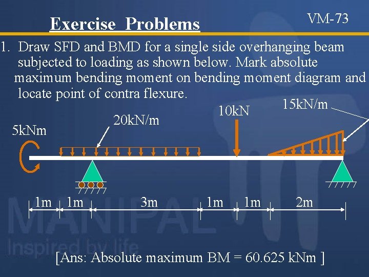
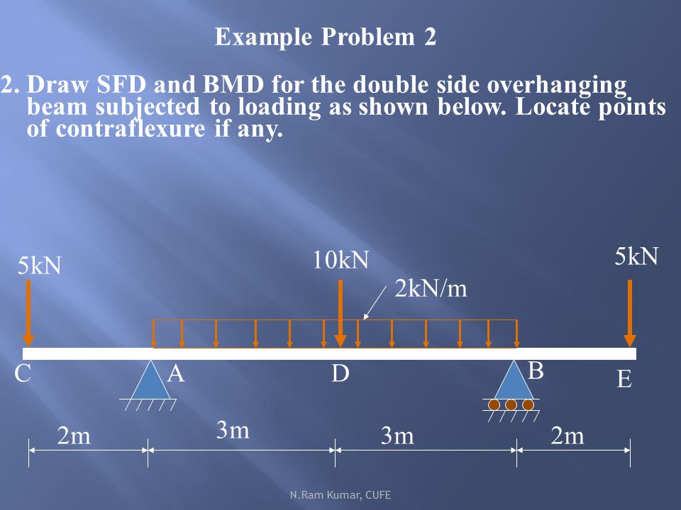
Unit Iii Bending Moment And Shear Force In Beams Ppt Download from slideplayer.com Sfd and bmd for overhanging beam point load & udl, mechanics of solids, (strength of materials). Derive the expression m/i=f/y=e/r 5. Concentrated loads, shear is constant between loading points and moment varies. About the beam calculator welcome to our free online bending moment and shear force diagram calculator which can generate the reactions, shear force diagrams (sfd) and bending moment diagrams (bmd) of a cantilever beam or simply supported beam. (bmd) shear force diagram (sfd) axial force diagram. For a beam whose left support is hinge and right support is roller. However, values of sf and bm can be verified at the support if support reactions are known. Problems on bending stress 1.
Add the forces (including reactions) normal to the beam on the one of the portion.
Lecture series on mechanics of solids by prof.m.s.siva kumar , department of applied mechanics ,i.i.t.madras. Consistent with beam theory is shown in f.1(b). Bmd(bending moment diagram ) is a diagram representing the variation of bending moment along the length of member.sfd(shear force diagram ) is diagram representing variation of shear force along the length of structural member.we draw sfd and bm. The beam also carries a u.d.l. Obtained by integrating this equation twice method is usable only if w is a continuous function of x (other cases not part of this course) classify the. Jahangirabad instiute of technology barabanki department of mechanical engineering elements of mechanical engineering ravi vishwakarma 31/12/16 ravi vishwakarma 1 2. Problems on bending stress 1. Beam guru.com is a online calculator that generates bending moment diagrams (bmd) and shear force diagrams (sfd), axial force diagrams (afd) for any statically determinate (most simply supported and cantilever beams) and statically indeterminate beams, frames and trusses. #sfd_bmd #sfd_bmd_continuous_beamhello friends,this video tutorial is on request of many people who wanted the sfd and bmd for continuous beam with udl and o. In sfd and bmd diagrams shear force or bending moment represents the ordinates, and the length of the beam represents the abscissa. Sfd and bmd:the shear force diagram (sfd)bending moment diagram(bmd)of a beam shows the variation of shear force such beam is shown in fig. Below are the beam formulas and their respective sfd's and bmd's a simply supported beam is the most simple arrangement of the structure. Sfd & bmd for simply supported beams.
Glulam beam to column connection bmd sfd. Sfd and bmd of simply supported beam gate questions part 2.


0 Komentar